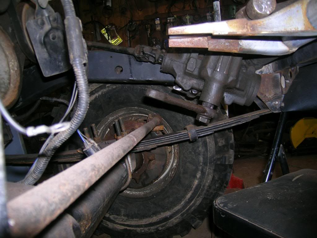
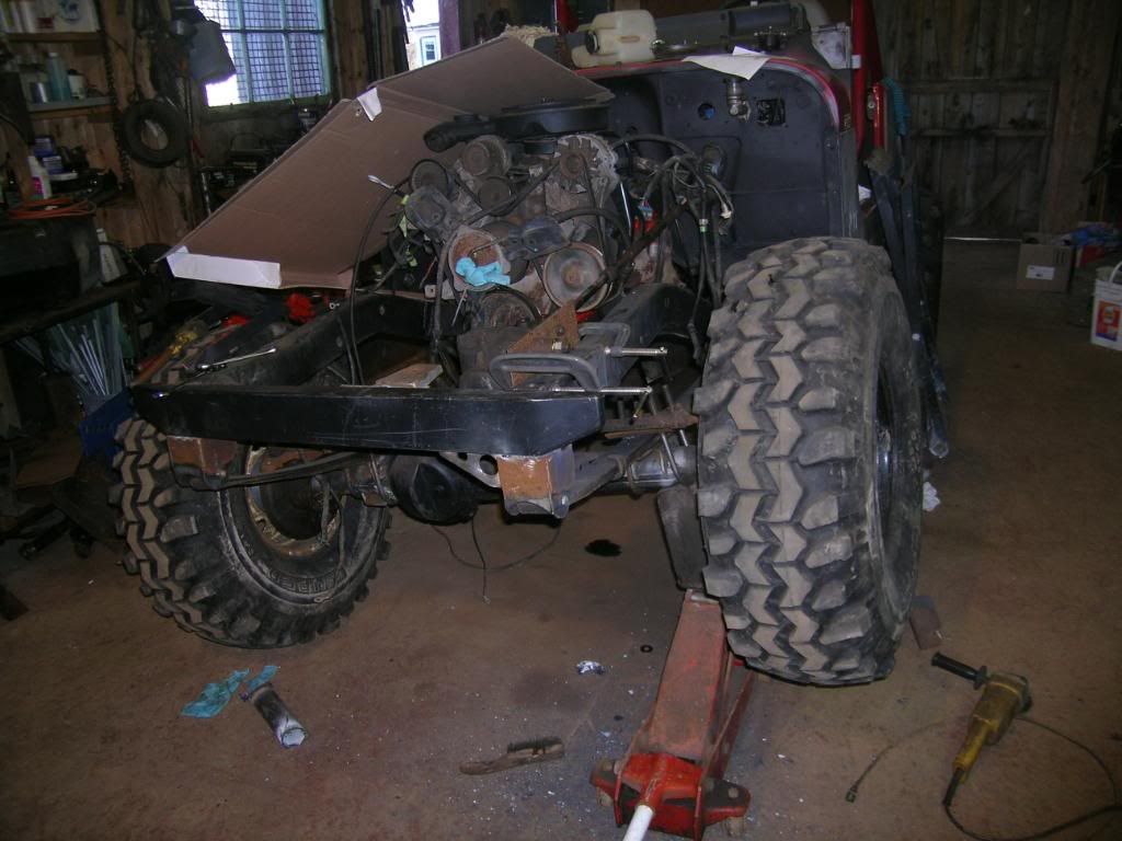
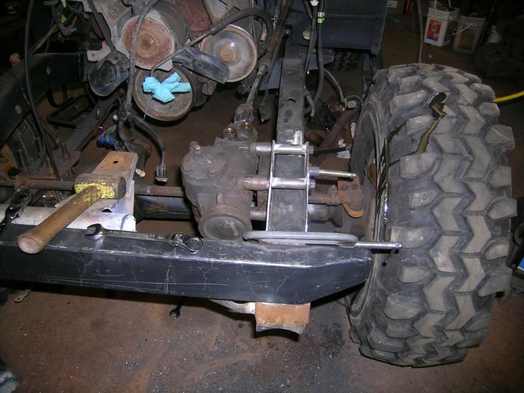
Spent a little time this weekend working on the heep. As you can see below, going to hi-steer with the axle pushed forward meant the pitman arm was going to get into the tie rod. Originally with the stock pitman arm there was only about 2" from the stock arm (without TRE on it) to the stock tie rod. I am going to a Trail Gear DOM tie rod which is bigger than stock so clearance was a pretty big issue.
I had hoped that I could use a CJ Pitman arm (which is flat) to get enough clearance between the two throughout the range of flex. As you can see there is some distance between the two but as you compress the drivers side you end up with about a half inch between the two with no tie rod end in the pitman arm.
I had been dragging my heels about doing a modification to the location of the steering box, not because I don't have to ability but was afraid of problems getting an inspection.
I also have a astro van steering box (Forward Throw) left over from the motor donor. It is a DIRECT bolt on hoses and everythig fits. BUT it puts the TRE hole in the pitman arm out about 10 or 11 inches from the center of the tie rod. I didn't like the kinda loading it would have put on the hi steer arms or the box itself. Some of the force would have been in the front to back direction as opposed to the side to side direction like its supposed to.
Heres the process of moving the steering box to a happy location.
I would like some feedback from the experienced fabbers. I feel that this is stronger than the stock configuration. But I am inviting criticism and comments due to the critical nature of the modification. Please feel free to comment.[/b][/i][/size]
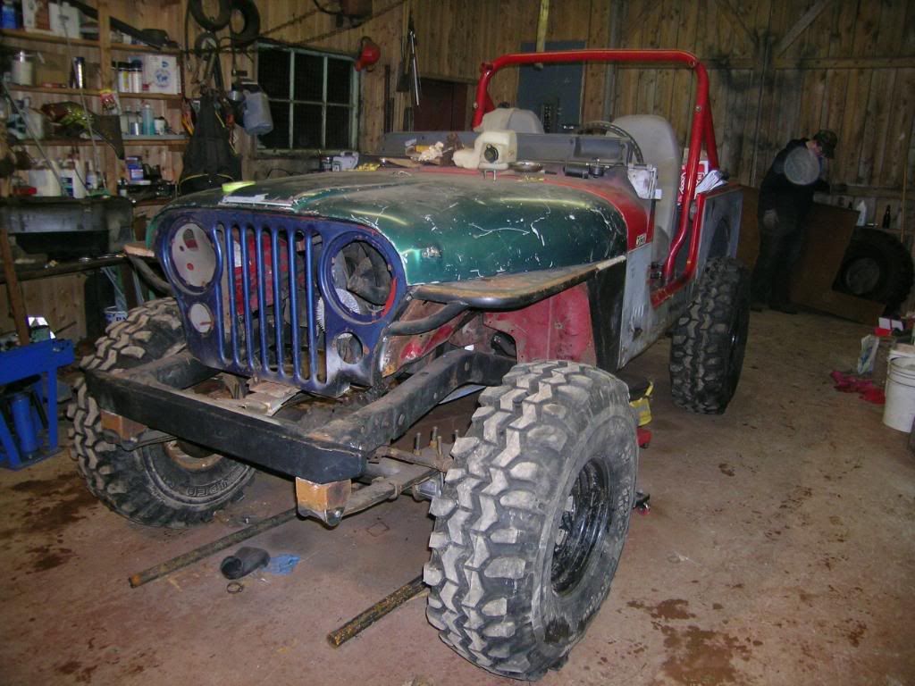
The front end started out looking like a normal YJ frame. Steering box tipped up at the back with the front hanging down to ram into things.
The drivers side of the grille support was mothballed. No close ups of my torching ability as it usually comes out looking like I dipped it in a lava flow.
Both Sides of the frame was cleaned up.
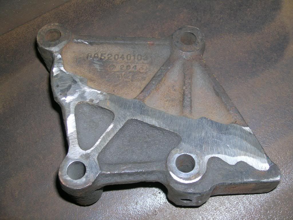
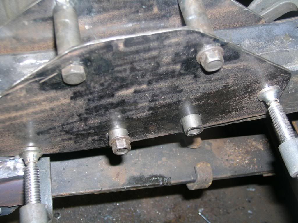
Mike had come up with the idea of taking the stock frame adapter and cutting the boss off that mounts to the bottom of the frame. (the sway bar mounts to is as well) There are 6 bolts in total on the adapter, 2 that are used to bolt it to the steering box (at the bottom) and the 2 at the top that go through the frame, and the 2 at the bottom that mount to the frame and the sway bar. So in stock config 2 bolts are in tension and 2 in shear. He figured put all 4 bolts in tension. I screwed around with the math and with the tensile strength of the a grade 8 (assumed stock) bolt at 15 900 lbs each and having 4 in use I can't see a problem with the hardware.
Here is the stock steering box adapter after mike had modified it.
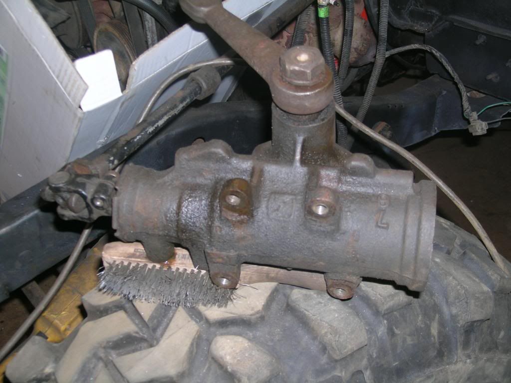
Steering box with the adapter taken off the back of it.
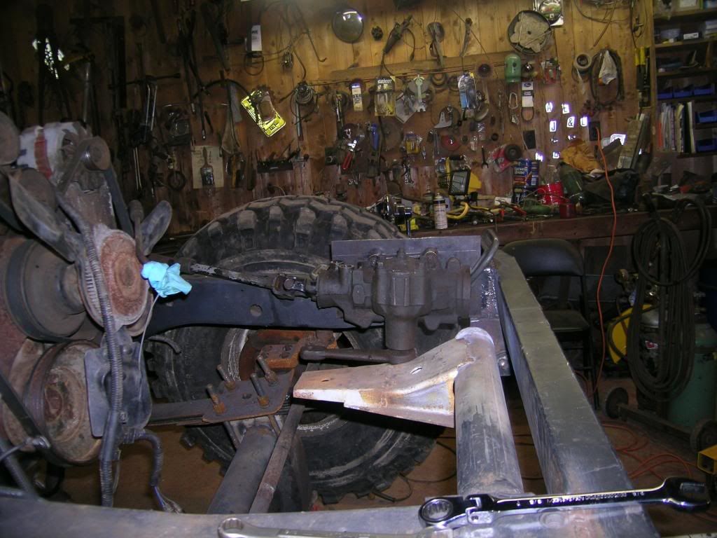
I left the steering shaft connected to the box and swung the whole assembly up. To see if it would work, I wanted to keep a stock steering shaft as the bearings go out of the bottom joint (as mine has) and someday hopefully I will be able to pick up a better one on the cheap. Or if I win the Super 7 I'll put on a chrome Borgenson one. Either way keeping it stock was important in my eyes.
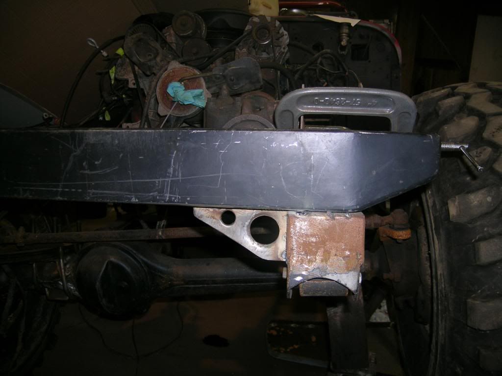
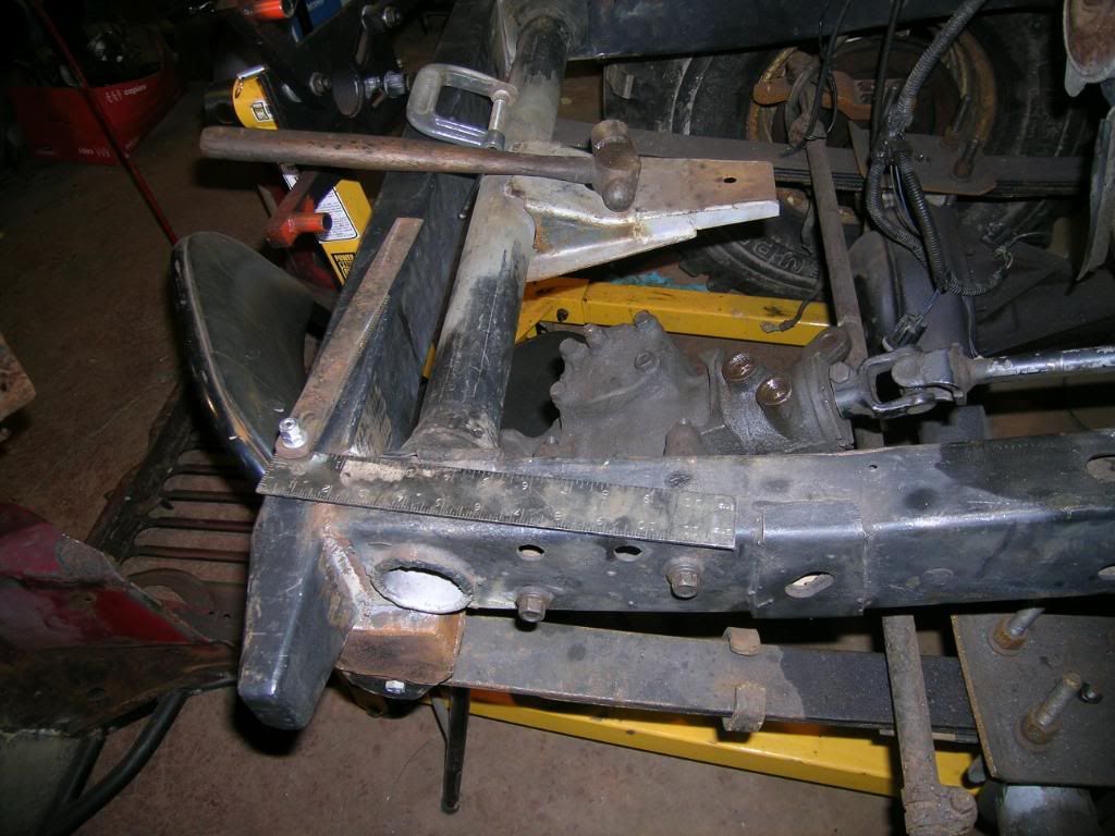
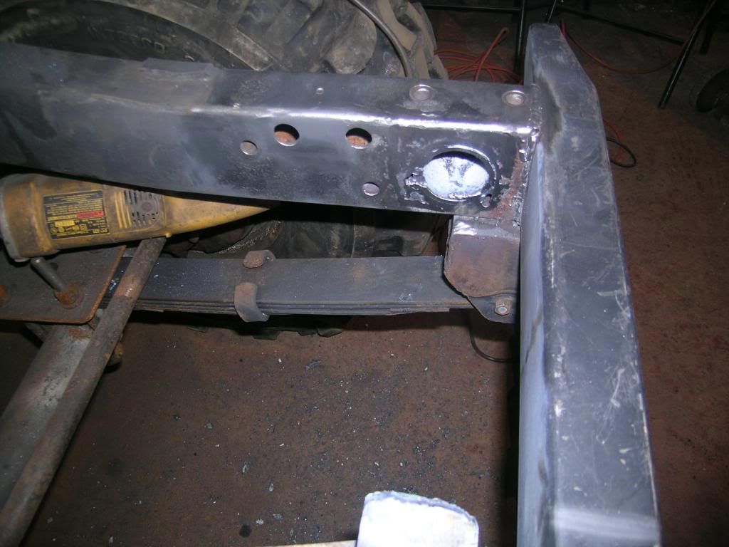
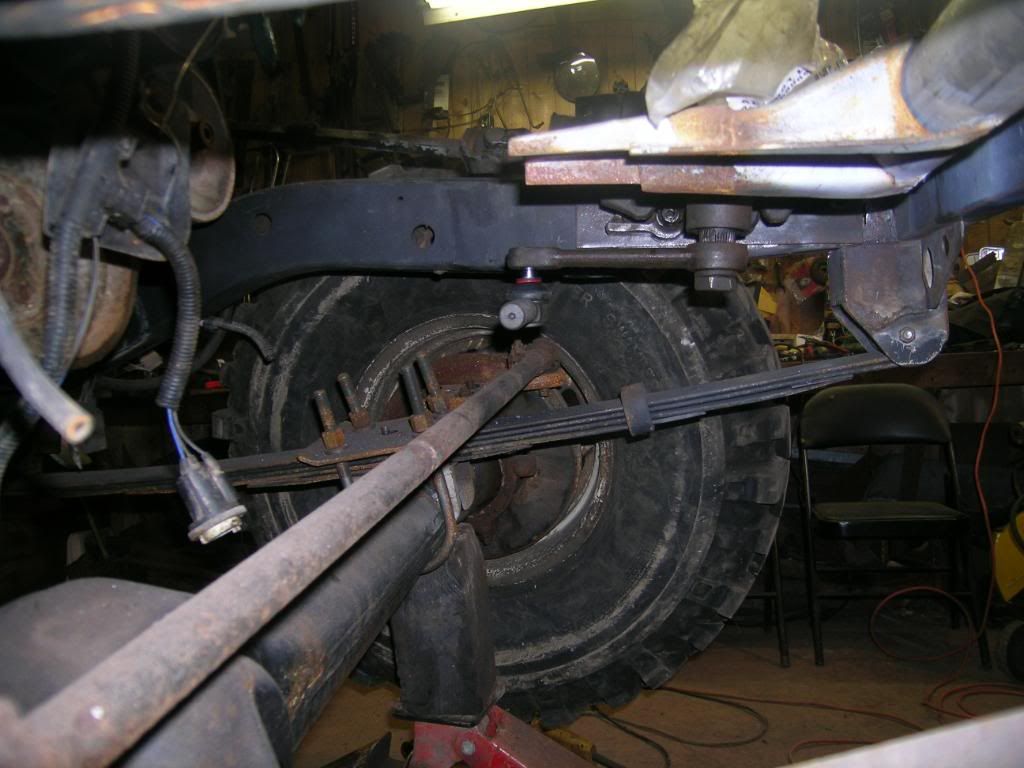
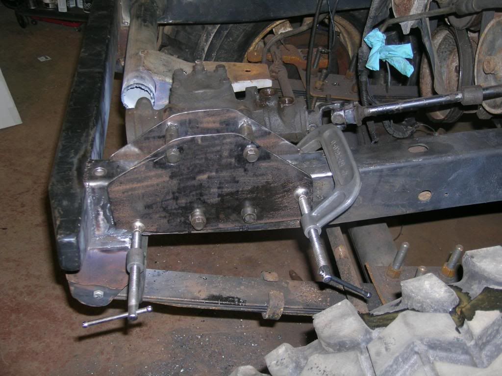
I cut a piece of 3/16 sheet and drilled 4 holes in it to match the steering box adapter. the steering box was bolted to the plate and then clamped to the frame for a beer and a think. The steering shaft joint had no chance of binding and the pitman arm was miles away fromt the tie rod now.
I did the floor jack flex test and there is no chance of interference. Sweet.
Standard operating procedure for Toyota is to use FJ 80 tie rod ends, they're big suckers and even under the flex there was lots of room. Also keeping the stock steering shaft as the box was moved up the radius of the steering shaft pushed it out. I can go back to the shorter YJ pitman arm now and it will clear in front of the tie rod. Leaves lots of options if I run into problems later.
Location is good. Time to work on the new mounting plates.
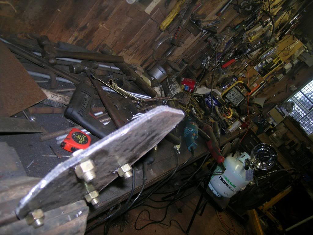
I duplicated the inside plate for the outside. All the free beer you can drink if you want to come clean my bench off and put everything away.
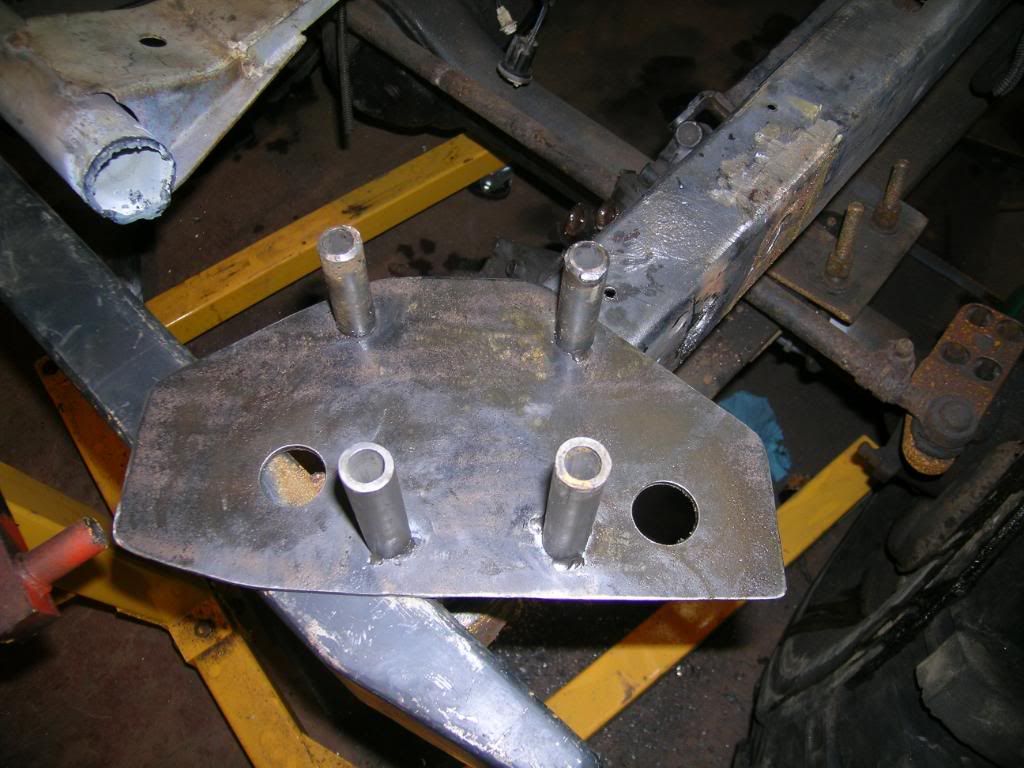
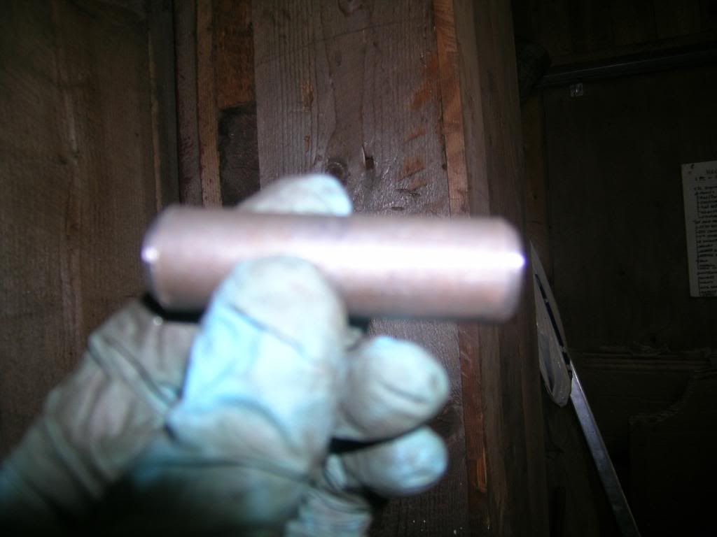
We had the right size tube for sleeving the bolt holes left over from some other exercize so it was straight ahead to making spacers to go between the 2 top bolt holes.
I chamfer the ends to make sure i have a good weld between the plate and the tube.
I got on a roll here and forgot to take pictures but I tack welded the top 2 sleeves to the inside plate making sure I kept everything square.
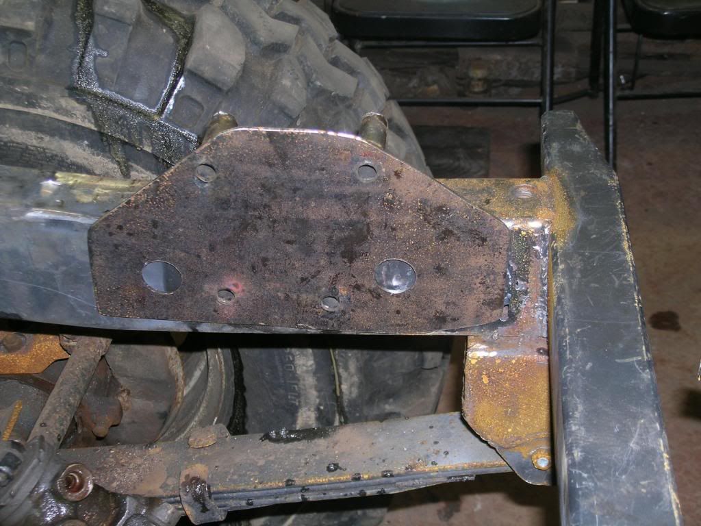
I test fit it back on the frame to make sure everything is still ok. It looked good so I marked the 2 bottom bolt holes on the frame on each side.
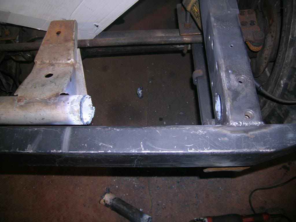
The sleeve material is less than 7/8", closer to a sloppy cut 3/4" hole, so I drilled a 7/8 hole on each side. The oversize hole allowed for some wiggle room in the alignment department. Fitment to the frame wasn't too critical as the tube is welded to the new plates and just passes through the original frame.
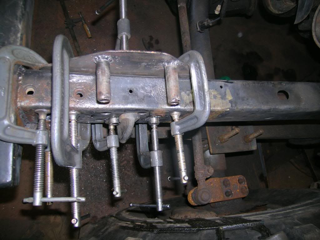
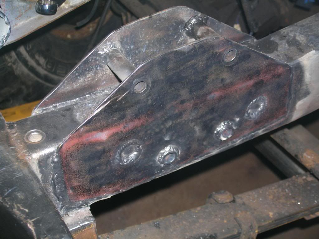
The bottom 2 sleves I left long to pass through the outside plate so I can just run a bead around them on the outside. The original frame is like this with the sleve proud of the surface and the weld around it on the outside. The bottom 2 sleves are tacked to the inside plate as well. The inside plate will have all 4 sleves welded to the inside of it. The top 2 sleves I can weld to the inside of the outer plate as I can get at them. The bottom 2 are welded to the outside of the outer plate as I cant get at the inside of them to weld.
This is basically where I stopped so I could gather some edumacated opinions. I can undo all this and go back to almost stock if someone were to say its no good. Nothing is welded up yet.
The only other pain from doing this is Ill now have to cut into the CJ grille more to clear the new setup. Hopefully it's low enough to keep out of the "waterfall" part of the grille (the slots).


 >Think that I would of parked it out back with the Ford ;D.Sits nice with the Q78's on it.


 That's about what I had in mind when we were spitballin' last weekend man. You're already going to box the top of the plates, but I think adding a gusset or 2 inside before you box it would be well served. And drill some more holes in the plates for rosette welds to the old frame. And I'll have to make a better detail of what I mentioned about the tow-hook mount.